目录
(2)R2与R5之间使用ppp的CHAP认证,R5为主认证方。
(1)R1、R2、R3构建一个MGRE环境,R1为中心站点。
四、配置NAT协议(easy IP)使得所有的PC可以访问R5环回
实验要求:
1、R5为ISP,只能进行IP地址配置,其所有地址均配为公有IP地址。
2、(1)R1和R5间使用PPP的PAP认证,R5为主认证方。
(2)R2与R5之间使用ppp的CHAP认证,R5为主认证方。
(3)R3与R5之间使用HDLC封装。
3、R1、R2、R3构建一个MGRE环境,R1为中心站点,R1、R4间为点到点的GRE。
4、整个私有网络基于RIP全网可达。
5、所有PC设置私有IP为源IP,可以访问R5环回,实现全网通。
实验拓扑图:
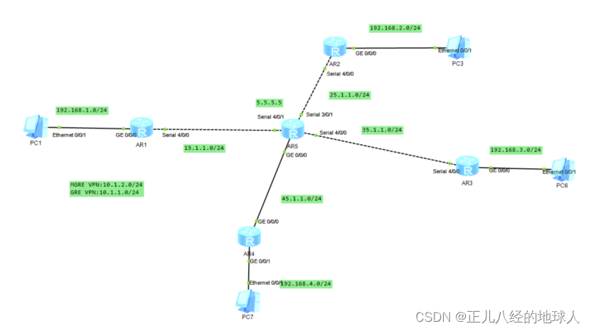
实验思路:
- 根据拓扑图配置所有设备的IP地址
- 将私网与公网分别搞通
- 在公网搞通的基础上进行PPP的pap和chap认证,以及DHLC验证
- 再创建GRE VPN和MGRE VPN
- 配置NAT协议使得所有的PC可以访问R5环回,实现全网通
实验步骤:
一、配IP地址
(1)配置所有设备接口的IP地址:
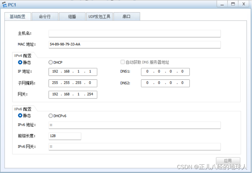
PC1:
PC3:

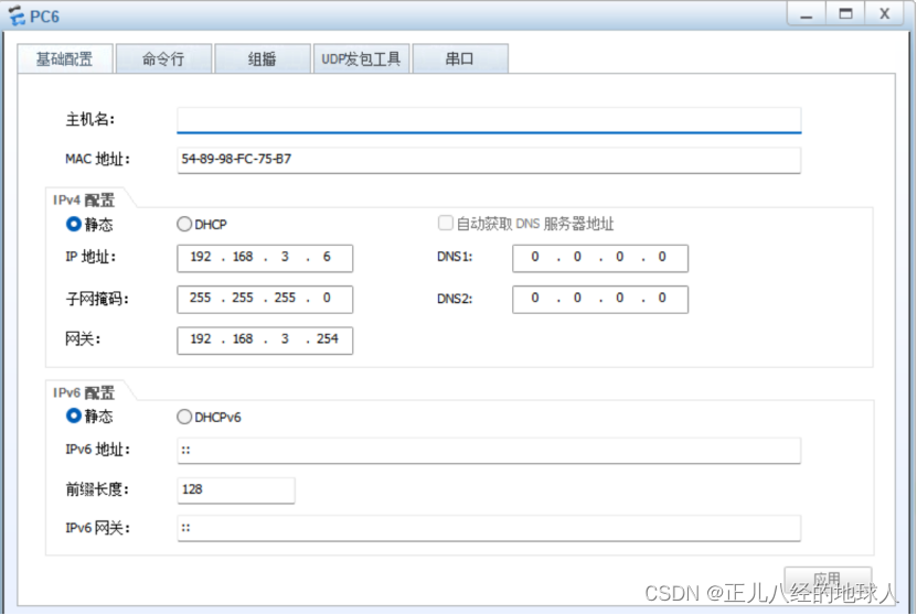
PC6:
PC7:

R1:

<Huawei>sys

[Huawei]sysn R1

[R1]int g 0/0/0

[R1-GigabitEthernet0/0/0]ip add 192.168.1.254 24

[R1-GigabitEthernet0/0/0]q

[R1]int Serial 4/0/0

[R1-Serial4/0/0]ip add 15.1.1.1 24

[R1-Serial4/0/0]q

[R1]dis ip int bri


R2:

<Huawei>sys

[Huawei]sysn R2

[R2]int g0/0/0

[R2-GigabitEthernet0/0/0]ip add 192.168.2.254 24

[R2-GigabitEthernet0/0/0]q

[R2]int Serial 4/0/0

[R2-Serial4/0/0]ip add 25.1.1.2 24

[R2-Serial4/0/0]q

[R2]dis ip int bri


R3:

<Huawei>sys

[Huawei]sysn R3

[R3]int g0/0/0

[R3-GigabitEthernet0/0/0]ip add 192.168.3.254 24

[R3-GigabitEthernet0/0/0]q

[R3]int Serial 4/0/0

[R3-Serial4/0/0]ip add 35.1.1.3 24

[R3-Serial4/0/0]q

[R3]dis ip int bri


R4:

<Huawei>sys

[Huawei]sysn R4

[R4]int g 0/0/0

[R4-GigabitEthernet0/0/0]ip add 45.1.1.4 24

[R4-GigabitEthernet0/0/0]int g 0/0/1

[R4-GigabitEthernet0/0/1]ip add 192.168.4.254 24

[R4-GigabitEthernet0/0/1]q

[R4]dis ip int bri


R5:

<Huawei>sys

[Huawei]sysn R5

[R5]int g0/0/0

[R5-GigabitEthernet0/0/0]ip add 45.1.1.5 24

[R5-GigabitEthernet0/0/0]q

[R5]int Serial 4/0/1

[R5-Serial4/0/1]ip add 15.1.1.5 24

[R5-Serial4/0/1]q

[R5]int Serial 3/0/1

[R5-Serial3/0/1]ip add 25.1.1.5 24

[R5-Serial3/0/1]q

[R5]int Serial 4/0/0

[R5-Serial4/0/0]ip add 35.1.1.5 24

[R5-Serial4/0/0]q

[R5]int l0

[R5-LoopBack0]ip add 5.5.5.5 24

[R5]dis ip int bri
(2)配置私网与公网接口的缺省路由使得公网可通:
R1:

[R1]ip route-static 0.0.0.0 0 15.1.1.5

R2:

[R2]ip route-static 0.0.0.0 0 25.1.1.5

R3:

[R3]ip route-static 0.0.0.0 0 35.1.1.5

R4:

[R4]ip route-static 0.0.0.0 0 45.1.1.5
测试一下:
示例:

R1的serial 4/0/0接口 ping R2 的serial 4/0/0接口

<R1>ping -a 15.1.1.1 25.1.1.2

  PING 25.1.1.2: 56  data bytes, press CTRL_C to break

    0.00% packet loss


R3的serial 4/0/0接口 ping R4 的g 0/0/0接口


<R3>ping -a 35.1.1.3 45.1.1.4

  PING 45.1.1.4: 56  data bytes, press CTRL_C to break

0.00% packet loss
测试通过!!!
二、PPP验证的PAP和CHAP认证 与 DHLC 认证
(1)R1和R5间使用PPP的PAP认证,R5为主认证方。
R5(主验证方):

[R5]aaa

[R5-aaa]local-user gxc password cipher gxc12345

[R5-aaa]local-user gxc service-type ppp

[R5-aaa]q

[R5]int Serial 4/0/1

[R5-Serial4/0/1]ppp authentication-mode pap

[R5-Serial4/0/1]q

[R5]

R1(被验证方):

[R1-Serial4/0/0]ppp pap local-user gxc password cipher gxc12345

[R1-Serial4/0/0]shutdown

[R1-Serial4/0/0]undo shutdown
(2)R2与R5之间使用ppp的CHAP认证,R5为主认证方。
R5(主验证方):

[R5-aaa]aaa

[R5-aaa]local-user gxc password cipher gxc12345

[R5-aaa]local-user gxc service-type ppp

[R5-aaa]q

[R5]int Serial 3/0/1

[R5-Serial3/0/1]ppp authentication-mode chap

[R5-Serial3/0/1]q

[R5]


R2(被验证方):

[R2-Serial4/0/0]ppp chap user gxc

[R2-Serial4/0/0]ppp chap password cipher gxc12345

[R2-Serial4/0/0]undo shutdown

[R2-Serial4/0/0]shutdown
(3)R3与R5之间使用HDLC封装。
R5:

[R5-Serial4/0/0]link-protocol hdlc


R3:

[R3-Serial4/0/0]link-protocol hdlc
三、再创建GRE VPN和MGRE VPN
MGRE VPN:10.1.2.0/24
GRE VPN:10.1.1.0/24
(1)R1、R2、R3构建一个MGRE环境,R1为中心站点。
隧道接口配置:
R1:

[R1]int Tunnel 0/0/0

[R1-Tunnel0/0/0]ip add 10.1.2.1 24

[R1-Tunnel0/0/0]tunnel-protocol gre p2mp

[R1-Tunnel0/0/0]source 15.1.1.1
# 配置NHRP(下一跳解析协议)

[R1-Tunnel0/0/0]nhrp network-id 100

[R1-Tunnel0/0/0]q

[R1]dis nhrp peer all


R2:

[R2]int Tunnel 0/0/0

[R2-Tunnel0/0/0]ip add 10.1.2.2 24

[R2-Tunnel0/0/0]tunnel-protocol gre p2mp

[R2-Tunnel0/0/0]source Serial 4/0/0

# 设置与NHRP服务器(Next Hop Resolution Protocol)的条目
[R2-Tunnel0/0/0]nhrp network-id 100

[R2-Tunnel0/0/0]nhrp entry 10.1.2.1 15.1.1.1 register

[R2-Tunnel0/0/0]q

[R2]dis nhrp peer all


R3:

[R3]int Tunnel 0/0/0

[R3-Tunnel0/0/0]ip add 10.1.2.3 24

[R3-Tunnel0/0/0]tunnel-protocol gre p2mp

[R3-Tunnel0/0/0]source Serial 4/0/0.

[R3-Tunnel0/0/0]nhrp network-id 100

[R3-Tunnel0/0/0]nhrp entry 10.1.2.1 15.1.1.1 register

[R3-Tunnel0/0/0]q

[R3]dis nhrp peer all
(2)R1、R4间为点到点的GRE。
R1:

[R1]int Tunnel 0/0/1

[R1-Tunnel0/0/1]ip add 10.1.1.1 24

[R1-Tunnel0/0/1]tunnel-protocol gre

[R1-Tunnel0/0/1]source 15.1.1.1

[R1-Tunnel0/0/1]destination 45.1.1.4


R4:

[R4]int Tunnel 0/0/1

[R4-Tunnel0/0/1]ip add 10.1.1.4 24

[R4-Tunnel0/0/1]tunnel-protocol gre

[R4-Tunnel0/0/1]source 45.1.1.4

[R4-Tunnel0/0/1]destination 15.1.1.1
(3)在R1到R5上配置路由协议(RIP)传递两端私网路由
R1:

[R1]rip 1

[R1-rip-1]version 2

[R1-rip-1]network 192.168.1.0

[R1-rip-1]network 10.0.0.0

[R1-rip-1]undo summary

[R1-rip-1]q

查看路由表中的rip信息

[R1]dis ip routing-table protocol rip

[R1]int Serial 4/0/0

关闭RIP水平分割:

[R1-Serial4/0/0]undo rip split-horizon

[R1]int tunnel 0/0/0

开启伪广播 :

[R1-Tunnel0/0/0]nhrp entry multicast dynamic


R2:

[R2]rip 1

[R2-rip-1]v 2

[R2-rip-1]undo summary

[R2-rip-1]network 192.168.2.0

[R2-rip-1]network 10.0.0.0

[R2-rip-1]q

[R2]dis ip routing-table protocol rip

[R2]int t0/0/0

[R2-Tunnel0/0/0]undo rip split-horizon

[R2-Tunnel0/0/0]q

[R2]


R3:

[R3]rip 1

[R3-rip-1]v  2

[R3-rip-1]undo summary

[R3-rip-1]network 192.168.3.0

[R3-rip-1]network 10.0.0.0

[R3-rip-1]q

[R3]dis ip routing-table protocol rip

[R3]int t0/0/0

[R3-Tunnel0/0/0]undo rip sp

[R3-Tunnel0/0/0]undo rip split-horizon

[R3-Tunnel0/0/0]q

[R3]


R4:

[R4]rip 1

[R4-rip-1]v 2

[R4-rip-1]undo summary

[R4-rip-1]network 192.168.4.0

[R4-rip-1]network 10.0.0.0

[R4-rip-1]q

[R4]
测试一下私网与公网是否已经是可通:
示例:

PC1 ping PC3:

PC>ping 192.168.2.3

Ping 192.168.2.3: 32 data bytes, Press Ctrl_C to break

  20.00% packet loss


PC1 ping PC6:

  PC>ping 192.168.3.6

Ping 192.168.3.6: 32 data bytes, Press Ctrl_C to break

  0.00% packet loss
测试通过!!!
四、配置NAT协议(easy IP)使得所有的PC可以访问R5环回
R1:

<R1>sys

[R1]acl 2000

[R1-acl-basic-2000]rule permit source 192.168.1.0 0.0.0.255

[R1-acl-basic-2000]q

[R1]int Serial 4/0/0

[R1-Serial4/0/0]nat outbound 2000

[R1-Serial4/0/0]q

[R1]


R2:

[R2]acl 2000

[R2-acl-basic-2000]rule permit source 192.168.2.0 0.0.0.255

[R2-acl-basic-2000]q

[R2]int Serial 4/0/0

[R2-Serial4/0/0]nat outbound 2000

[R2-Serial4/0/0]q

[R2]


R3:

<R3>sys

[R3]acl 2000

[R3-acl-basic-2000]rule permit source 192.168.3.0 0.0.0.255

[R3-acl-basic-2000]q

[R3]int Serial 4/0/0

[R3-Serial4/0/0]nat outbound 2000

[R3-Serial4/0/0]q

[R3]


R4:

<R4>sys

[R4]acl 2000

[R4-acl-basic-2000]rule permit source 192.168.4.0 0.0.0.255

[R4-acl-basic-2000]q

[R4]int g0/0/0

[R4-GigabitEthernet0/0/0]nat outbound 2000

[R4-GigabitEthernet0/0/0]q

[R4]
测试一下:
示例:

PC1 ping R5的环回路由:

PC>ping 5.5.5.5

  0.00% packet loss


PC7 ping R5 的环回路由:

PC>ping 5.5.5.5

Ping 5.5.5.5: 32 data bytes, Press Ctrl_C to break

  20.00% packet loss
测试通过!!!


