5.2.1 实验1:配置IPv4静态路由
1、实验目的
通过本实验可以掌握:
- 配置带下一跳地址的IPv4静态路由的方法。
- 配置带送出接口的IPv4静态路由的方法。
- 配置总结IPv4静态路由的方法。
- 配置浮动IPv4静态路由的方法。
- 代理 ARP的作用。
- 路由表的含义。
- 扩展ping命令的使用方法。
2、实验拓扑
配置IPv4静态路由的实验拓扑如图5-1所示。
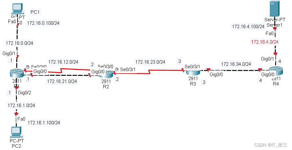
图5-1 配置IPv4静态路由的实验拓扑
3、实验拓扑
(1)配置路由器R1
R1(config)#interface gigabitEthernet 0/0
R1(config-if)#ip address 172.16.21.1 255.255.255.0
R1(config-if)#no shutdown
R1(config-if)#exit
R1(config)#interface gigabitEthernet 0/1
R1(config-if)#ip address 172.16.0.1 255.255.255.0
R1(config-if)#no shutdown
R1(config-if)#exit
R1(config)#interface gigabitEthernet 0/2
R1(config-if)#ip address 172.16.1.1 255.255.255.0
R1(config-if)#no shutdown
R1(config-if)#exit
R1(config)#interface serial 0/3/0
R1(config-if)#ip address 172.16.12.1 255.255.255.0
R1(config-if)#no shutdown
R1(config)#ip route 0.0.0.0 0.0.0.0 serial 0/3/0 100
//配置带送出接口的静态默认路由,管理距离设置为100,默认为1,由于串行链路速率比以太网慢得多,所以,该路由作为备份路由,即浮动静态路由
R1(config)#ip route 0.0.0.0 0.0.0.0 172.16.21.2
//配置带下一跳地址的静态默认路由,该路由作为主路由
【技术要点】
配置静态路由的命令是:
Router(config)#ip route prefix mask {address|interface[address]} [distance] [permanent]命令参数含义如下所诉。
- prefix:目的网络地址。
- mask:目标网络的子网掩码。可对此子网掩码进行修改,以使汇总一组网络。
- address:将数据包转发到目的网络时使用的下一跳IP地址。
- interface:将数据包转发到目的网络时使用的本地送出接口。
- distance:静态路由条目的管理距离,默认为1。
- permanent:正常情况下,如果和静态路由条目相关联的接口进入down状态,该静态路由会被从路由表中删除。permanent参数的含义是即使和静态路由条目相关联的接口进入down状态,路由条目也不会从路由表中消失。
(2)配置路由器R2
R2(config)#interface gigabitEthernet 0/0
R2(config-if)#ip address 172.16.21.2 255.255.255.0
R2(config-if)#no shutdown
R2(config-if)#exit
R2(config)#interface serial 0/3/0
R2(config-if)#ip address 172.16.12.2 255.255.255.0
R2(config-if)#no shutdown
R2(config-if)#exit
R2(config)#interface serial 0/3/1
R2(config-if)#ip address 172.16.23.2 255.255.255.0
R2(config-if)#no shutdown
R2(config-if)#exit
R2(config)#ip route 172.16.0.0 255.255.255.0 172.16.21.1
R2(config)#ip route 172.16.1.0 255.255.255.0 172.16.21.1
R2(config)#ip route 172.16.0.0 255.255.255.0 serial 0/3/0 100
R2(config)#ip route 172.16.1.0 255.255.255.0 serial 0/3/0 100
R2(config)#ip route 172.16.4.0 255.255.255.0 serial 0/3/1
R2(config)#ip route 172.16.34.0 255.255.255.0 serial 0/3/1
(3)配置路由器R3
R3(config)#interface gigabitEthernet 0/0
R3(config-if)#ip address 172.16.34.3 255.255.255.0
R3(config-if)#no shutdown
R3(config-if)#exit
R3(config)#interface serial 0/3/1
R3(config-if)#ip address 172.16.23.3 255.255.255.0
R3(config-if)#no shutdown
R3(config-if)#exit
R3(config)#ip route 172.16.0.0 255.255.254.0 serial 0/3/1
//将到172.16.0.0/24 和172.16.1.0/24 的静态路由手工总结为1条,掩码为/23
R3(config)#ip route 172.16.12.0 255.255.255.0 serial 0/3/1
R3(config)#ip route 172.16.21.0 255.255.255.0 serial 0/3/1
R3(config)#ip route 172.16.4.0 255.255.255.0 172.16.34.4
(4)配置路由器R4
R4(config)#interface gigabitEthernet 0/0
R4(config-if)#ip address 172.16.34.4 255.255.255.0
R4(config-if)#no shutdown
R4(config-if)#exit
R4(config)#interface gigabitEthernet 0/1
R4(config-if)#ip address 172.16.4.4 255.255.255.0
R4(config-if)#no shutdown
R4(config-if)#exit
R4(config)#ip route 0.0.0.0 0.0.0.0 172.16.34.3
//由于R4到外部网络只有一个出口,配置默认静态路由比较适合
4、实验调试
(1)查看接口IP地址和状态,确保直连链路的连通性
R1#show ip interface brief | exclude unassigned
Interface              IP-Address      OK? Method Status                Protocol
GigabitEthernet0/0     172.16.21.1     YES manual up                    up
GigabitEthernet0/1     172.16.0.1      YES manual up                    up
GigabitEthernet0/2     172.16.1.1      YES manual up                    up
Serial0/3/0            172.16.12.1     YES manual up                    up
(2)查看路由
1、查看路由器R1的路由表
R1#show ip route
Codes: L - local, C - connected, S - static, R - RIP, M - mobile, B - BGP
       D - EIGRP, EX - EIGRP external, O - OSPF, IA - OSPF inter area
       N1 - OSPF NSSA external type 1, N2 - OSPF NSSA external type 2
       E1 - OSPF external type 1, E2 - OSPF external type 2, E - EGP
       i - IS-IS, L1 - IS-IS level-1, L2 - IS-IS level-2, ia - IS-IS inter area
       * - candidate default, U - per-user static route, o - ODR
       P - periodic downloaded static route

Gateway of last resort is 172.16.21.2 to network 0.0.0.0

     172.16.0.0/16 is variably subnetted, 8 subnets, 2 masks
C       172.16.0.0/24 is directly connected, GigabitEthernet0/1
//直连网络路由,管理距离为0,度量值为0
L       172.16.0.1/32 is directly connected, GigabitEthernet0/1
//本地路田,管理距离为0,度量值为0,IOS版本15以后路由表中会出现以路由器本地活动的接口地址为目标网络的/32主机路由
C       172.16.1.0/24 is directly connected, GigabitEthernet0/2
L       172.16.1.1/32 is directly connected, GigabitEthernet0/2
C       172.16.12.0/24 is directly connected, Serial0/3/0
L       172.16.12.1/32 is directly connected, Serial0/3/0
C       172.16.21.0/24 is directly connected, GigabitEthernet0/0
L       172.16.21.1/32 is directly connected, GigabitEthernet0/0
S*   0.0.0.0/0 [1/0] via 172.16.21.2
//*表示默认,/0掩码表明只需要有零位匹配(即无须匹配)。只要不存在更加精确的匹配,则默认静态路由将与所有数据包匹配,此路由管理距离为1,度量值为0
以上输出表明,路由器R1的路由表中包含4条直连路由、4条本地路由和1条静态默认路由条目。输出表明路由表中并没有出现出接口为S0/0/0的静态默认路由,因为其管理距离为100,大于采用下一跳地址为172.16.21.2的静态默认路由的管理距离1,对于同一条路由,路由器会把管理距离小的路由条目填充到路由表中。而出接口为S0/0/0 的静态默认路由是浮动静态路由,起到备份作用。接下来看一下浮动静态路由是如何工作的?
首先模拟网络故障(在路由器R1的G0/0接口上执行 shutdown命令,关闭接口),主链路中断,此时浮动静态路由会出现在R1路由表中,如下所示:
R1#show ip route static | include 0.0.0.0/0
S*   0.0.0.0/0 is directly connected, Serial0/3/0
//路由器R1选择出接口为S0/3/0的静态默认路由,以下命令可以查看路由条目的详细信息
R1#show ip route 0.0.0.0
Routing entry for 0.0.0.0/0, supernet
Known via "static", distance 100, metric 0 (connected), candidate default path
//路由条目管理距离为100
  Routing Descriptor Blocks:
  * directly connected, via Serial0/3/0        //路由条目送出接口
      Route metric is 0, traffic share count is 1
接着模拟网络故障恢复(在路由器R1的G0/0接口上执行no shutdown命令,开启接口),,此时查看R1路由表:
R1#show ip route static | include 0.0.0.0/0
S*   0.0.0.0/0 [1/0] via 172.16.21.2
//路由器R1重新选择下一跳地址为172.16.21.2的静态默认路由,而出接口为S0/3/0的静态默认路由继续起到备份作用
2、查看路由器R2的路由表。
R2#show ip route
(此处路由代码部分省略)
     172.16.0.0/16 is variably subnetted, 10 subnets, 2 masks
S       172.16.0.0/24 [1/0] via 172.16.21.1
S       172.16.1.0/24 [1/0] via 172.16.21.1
S       172.16.4.0/24 is directly connected, Serial0/3/1
C       172.16.12.0/24 is directly connected, Serial0/3/0
L       172.16.12.2/32 is directly connected, Serial0/3/0
C       172.16.21.0/24 is directly connected, GigabitEthernet0/0
L       172.16.21.2/32 is directly connected, GigabitEthernet0/0
C       172.16.23.0/24 is directly connected, Serial0/3/1
L       172.16.23.2/32 is directly connected, Serial0/3/1
S       172.16.34.0/24 is directly connected, Serial0/3/1
【技术要点】
在路由器R2上,当有去往PC2 ( 172.16.1.100)的数据包到达时,它是怎样查找路由表的呢?首先R2通过路由条目S 172.16.1.0/24 [1/0] via 172.16.21.1确定到达目的地的下一跳的IP地址是172.16.21.1,这只是第一步查找,然后它将第二次搜索路由表,以查找与172.16.21.1匹配的路由对应的出接口,IP地址172.16.21.1与直连网络172.16.21.0/24 的路由条目(C 172.16.21.0 is directly connected, GigabitEthernet0/0)相匹配,送出接口为G0/0,第二次查找获知数据包将从该接口转发出去,上述查找过程称为递归查找。
请注意虽然带送出接口的静态路由显示为直连( directly connected ),但是管理距离默认情况下是1,可以通过如下命令来验证:
R2#show ip route 172.16.4.0
Routing entry for 172.16.4.0/24
Known via "static", distance 1, metric 0 (connected)    //静态路由条目管理距离为1
  Routing Descriptor Blocks:
  * directly connected, via Serial0/3/1
      Route metric is 0, traffic share count is 1
3、查看路由器R3的路由表。
R3#show ip route static    //参数static表示只查看路由表中的静态路由条目
(此处路由代码部分省略)
     172.16.0.0/16 is variably subnetted, 8 subnets, 3 masks
S       172.16.0.0/23 is directly connected, Serial0/3/1     //总结静态路由
S       172.16.4.0/24 [1/0] via 172.16.34.4
S       172.16.12.0/24 is directly connected, Serial0/3/1
S       172.16.21.0/24 is directly connected, Serial0/3/1
【技术要点】
将多条静态路由可以总结成一条静态路由必须同时满足下面的条件:
- 目的网络地址可以总结成一个网络地址,最好精确总结,避免路由黑洞;
- 多条静态路由都使用相同的送出接口或下一跳IP地址。
4、查看路由器R4的路由表
R4#show ip route static
S*   0.0.0.0/0 [1/0] via 172.16.34.3
【技术要点】
带送出接口的静态路由条目后面直接跟着送出接口,路由器只需要查找路由表一次,便能将数据包转发到送出接口。从这点来讲,查找路由表效率比查找带下一跳地址路由条目要高。因此使用送出接口配置的静态路由是大多数串行点对点网络(如 HDLC和 PPP封装)的理想选择。
修改路由器R4 的静态默认路由的配置为送出接口方式配置,说明为什么以太网中配置静态路由条目要选择下一跳地址方式,配置如下:
R4(config)#no ip route 0.0.0.0 0.0.0.0 172.16.34.3
R4(config)#ip route 0.0.0.0 0.0.0.0 gigabitEthernet 0/0
%Default route without gateway, if not a point-to-point interface, may impact performance
//告警信息的意思是静态默认路由没有网关,如果不是点到点接口,可能会影响性能。
对于以太网,如果要成功封装以太网帧,必须通过ARP协议完成二层的MAC地址和三层的P地址的映射。如果采用带下一跳地址配置静态路由,ARP请求广播数据包的内容是询问下一跳地址的MAC地址,因此下一跳路由器会用自己以太网接口的 MAC地址应答ARP。但是在以太网中,如果采用的是带送出接口的静态路由的配置,如果在R4的ARP表中没有相应的ARP条目,而发出的ARP广播数据包没有设备回复,则将不能成功封装以太网帧。但是在默认情况下,路由器的以太网接口都启用了ARP的代理功能,所以当R4发出 ARP查询时,R3收到ARP查询后,会查看自己的路由表,如果路由表中有目的地址的路由条目,则用自己的以太网接口G0/0的MAC地址进行响应,使得R4可以成功封装以太网帧。假如关闭路由器R3的以太网接口G0/0的ARP代理功能,并打开debug,将看到封装失败的信息,操作如下:
R3上的配置
R3(config)#interface gigabitEthernet 0/0
R3(config-if)#no ip proxy-arp           //关闭ARP代理功能

R4上的配置
R4#debug ip packet                      //打开debug功能
R4#clear arp                            //清空arp表
R4#ping 172.16.1.1

Type escape sequence to abort.
Sending 5, 100-byte ICMP Echos to 172.16.1.1, timeout is 2 seconds:

IP: tableid=0, s=172.16.34.4 (local), d=172.16.1.1 (GigabitEthernet0/0), routed via RIB

IP: s=172.16.34.4 (local), d=172.16.1.1 (GigabitEthernet0/0), len 128, sending

IP: s=172.16.34.4 (local), d=172.16.1.1 (GigabitEthernet0/0), len 128, encapsulation failed
//数据包封装失败
【提示】
对于带送出接口的静态路由配置,如果出接口为以太网接口,建议同时使用下一跳地!和送出接口来配置,如下所示:
R4(config)#ip route 0.0.0.0 0.0.0.0 gigabitEthernet 0/0 172.16.34.3
(3)动态查看路由表的添加或删除过程
以下是通过在路由器R1上将G0/0接口关闭,然后再开启,查看路由器Rl路由表的动态添加和删除过程。
R1#debug ip routing //开启debug命令
1、关闭接口,查看路由删除过程。
R1(config)#interface gigabitEthernet 0/0
R1(config-if)#shutdown
RT: interface GigabitEthernet0/0 removed from routing table
RT: del 172.16.21.0 via 0.0.0.0, connected metric [0/0]

RT: delete network route to 172.16.21.0

RT: NET-RED 172.16.21.0/24

RT: del 0.0.0.0 via 172.16.21.2, static metric [1/0]

RT: delete network route to 0.0.0.0

RT: NET-RED 0.0.0.0/0

RT: SET_LAST_RDB for 0.0.0.0/0

    NEW rdb: is directly connected


RT: add 0.0.0.0/0 via 0.0.0.0, static metric [100/0]

RT: NET-RED 0.0.0.0/0
RT: del 172.16.21.1 via 0.0.0.0,  metric [0/0]

RT: delete network route to 172.16.21.1

RT: NET-RED 172.16.21.1/32

RT: del 0.0.0.0 via 172.16.21.2, static metric [1/0]

RT: NET-RED 0.0.0.0/0
2、开启接口,查看路由添加过程
R1(config)#interface gigabitEthernet 0/0
R1(config-if)#no shutdown
RT: interface GigabitEthernet0/0 added to routing table
RT: SET_LAST_RDB for 172.16.21.0/24

    NEW rdb: is directly connected


RT: add 172.16.21.0/24 via 0.0.0.0, connected metric [0/0]

RT: NET-RED 172.16.21.0/24
RT: SET_LAST_RDB for 0.0.0.0/0

    NEW rdb: via 172.16.21.2


RT: add 0.0.0.0/0 via 172.16.21.2, static metric [1/0]

RT: NET-RED 0.0.0.0/0
RT: SET_LAST_RDB for 172.16.21.1/32

    NEW rdb: is directly connected


RT: add 172.16.21.1/32 via 0.0.0.0,  metric [0/0]

RT: NET-RED 172.16.21.1/32
(4)使用扩展 ping 命令测试连通性
标准 ping命令使用的都是默认参数,而扩展ping命令允许设置具体的参数,功能更加强大。注意在命令执行过程中,[]内的值即为 ping命令的默认值,如果选择默认值,直接回车即可。
R1#ping
Protocol [ip]:
Target IP address: 172.16.4.100
Repeat count [5]:
Datagram size [100]:
Timeout in seconds [2]:
Extended commands [n]: y
Source address or interface: 172.16.1.1
Type of service [0]:
Set DF bit in IP header? [no]:
Validate reply data? [no]:
Data pattern [0xABCD]:
Loose, Strict, Record, Timestamp, Verbose[none]:
Sweep range of sizes [n]:
Type escape sequence to abort.
Sending 5, 100-byte ICMP Echos to 172.16.4.100, timeout is 2 seconds:
Packet sent with a source address of 172.16.1.1
...!.
Success rate is 20 percent (1/5), round-trip min/avg/max = 3/3/3 ms

R1#


